Hydraulic Fracturing Engineering and Software Solution, for Your Most Challenging Reservoirs.

Providing clients with Hydraulic Fracture Engineering, Software, and Training Solutions for more than 30 years
US HEADQUARTERS
7146 S. Braden Avenue, Suite 102
Tulsa, Ok 74136
Contact: Alexandra Jalili
+ 1 918 496 2071
INFO@NSITECH.COM
GLOBAL
BRAZIL OFFICE
Contact: Carlos Eiffel Arbex Belem
+55 21 2262 9651
CARLOS@IESBRAZIL.COM.BR
CHINA OFFICE
Contact: Dr. Peter Wang
United States Contact
+1 512 258 0388
ZWANG@IUTGROUP.COM
Beijing Contact
010 6446 2601
ANDYTECH2008@126.COM
Tianjin Contact
022 2922 1211
15910754196
ANDYTECH2008@126.COM
StimPlan™ is a registered trademark of NSI Technologies, LLC.
Copyright 2019 NSI Technologies, LLC

StimPlan™™
StimPlan™ V8 - Hydraulic Fracturing Software Tech Note: The Power to Optimize Your Frac Design
There is no way to know in advance the “optimum” fracture design. Previously, it took too much time to simulate all the variable combinations that impact fracture propagation. Setting up and running large numbers of simulations one at a time was not practical. With StimPlan™ V8 Cloud, you now have the ability to run dozens of designs in less time than you previously spent completing a single simulation—without the cost of adding hardware!
Our Midland Basin case study showcases how StimPlan™ V8 Cloud can be utilized to improve frac design. When first developing an area, operators typically apply treatment designs that are analogous to their neighbors’. But given the inherent complexity and stress heterogeneity of these unconventional plays, that’s often not the best practice.

With StimPlan™ V8 Cloud, you can mitigate the uncertainty by simulating all possible scenarios ahead of the drill bit, thereby avoiding the costs of using the “trial and error” method of drilling and completing wells to optimize the design.
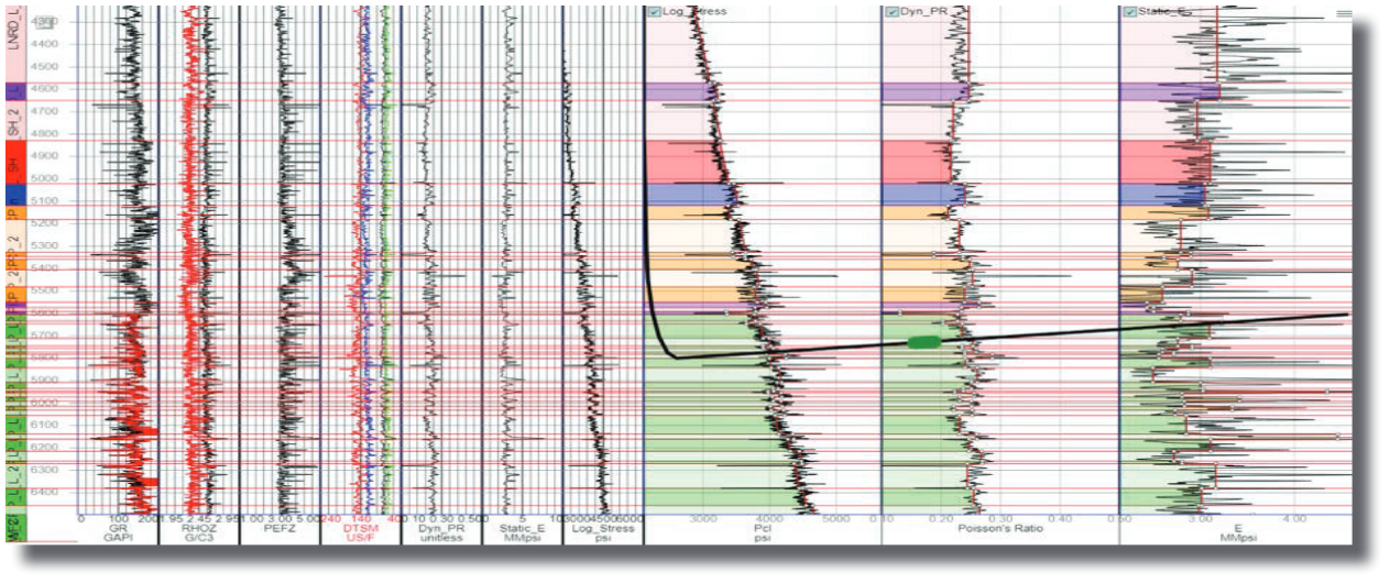
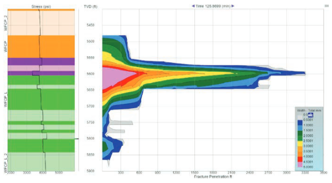
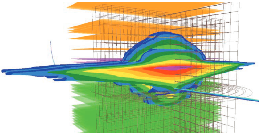
Our Midland Basin case study showcases how StimPlan™ V8 Cloud can be utilized to optimize frac design. As is typical for the Midland Basin and other unconventional reservoirs, this case study has a complex geological system,  requiring detailed finite element layering to accurately model. StimPlan™ V8’s flexible 3-D grid generation is much more adept than a fixed-grid approach for modeling such stratigraphically complex reservoirs.
With StimPlan™ V8 Cloud we were able to quickly vary and test several critical factors in our case study that influence fracture length and height growth, namely landing depths, pump rate, and the amount of fluid and proppant pumped. Other factors, such as fluid rheology and proppant type, could have easily been added to the variable matrix.
| Landing Depth (ft) | 5750 | 5800 | 5850 | 5900 | 5950 | 6000 |
|---|---|---|---|---|---|---|
| Pump Rate per Cluster (bpm) | 15 | 20 | 25 | 30 | ||
| Sand Valume per Cluster (lbs) | 62,500 | 93,750 | 125,000 |

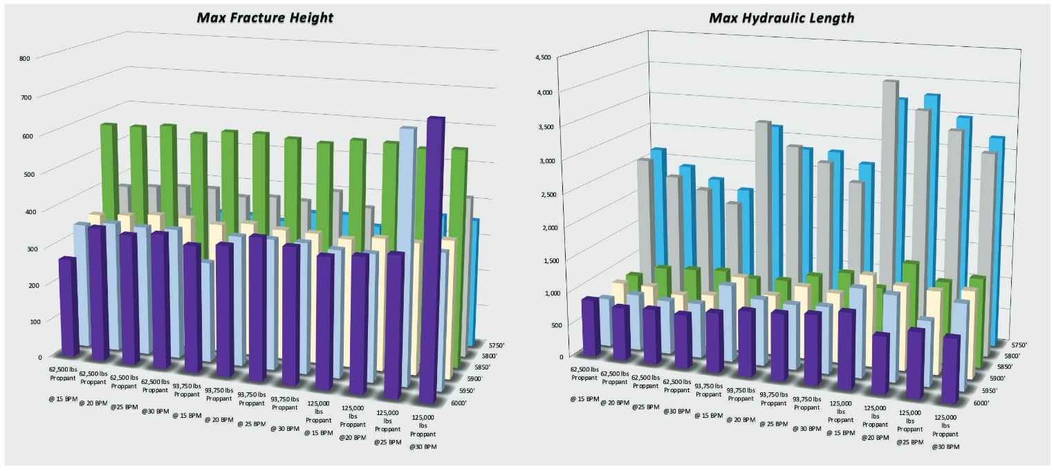
The column charts below show Frac Length and Frac Height vs Pump Schedule and Landing Depth. Clearly Frac Length grows substantially with the shallower landing depth cases, indicating a risk of slamming into the adjacent wells. Less dramatic, but still significant differences in frac geometry occur with changes in pump rate and volume with the greater landing depths.

Such insight would not be possible by running just a handful of simulations. With StimPlan™ V8 Cloud, all 72 of the simulations used to generate these charts ran in less than an hour—about 0.5% of the time that would have been required to run on StimPlan™ V7.
Make the transition from estimation to optimization with more accuracy and speed.
 The first step to design the best well is to find the best possible outcome for a single cluster. 72 scenarios from the parameters above were modeled to narrow in on THE ONE. All 72 simulations were completed in less than ONE hour with StimPlan™ V8 cloud-based simultaneous simulation capability.
 Once the best cluster design is achieved, the next step is to optimize each stimulation stage. Utilizing the best design out of the 72 simulations, parallel simulations are run to converge on the optimal number of clusters and ideal cluster spacing. In this case study, stages with three to five clusters were evaluated with spacing ranging from 50 ft to 75ft. With the power of StimPlan™ V8 Cloud, complete stage optimization is achieved in a day.
CONTINUING TO PUSH THE BOUNDARIES OF MULTIPLE CORE PROCESSING DON’T SACRIFICE DETAIL AND ACCURACY FOR SPEED. NOW YOU CAN HAVE IT ALL.
Whether Running StimPlan™ V8’s proprietary 3D finite element simulator in the cloud, or on your local, multi-core machine; the processing times have been significantly decreased—without sacrificing any of the analytical rigor that has distinguished StimPlan™ V8 from other frac models that take shortcuts to run faster. With StimPlan™ V8 Cloud, not only is the run time for each simulation significantly faster, overall project completion time is RADICALLY REDUCED because you can now run dozens of simulations simultaneously with almost no burden on your computer. It is really amazing.
StimPlan™ V8 realizes the potential and competitive advantage of the cloud-based computing environment with many improvements made to the core software, enabling HIGHLY LAYERED AND SMALL GRID simulations to be completed many times faster than previous versions.
You no longer have to sacrifice analytical rigor for speed. The more complex the simulations, the greater the time savings with New StimPlan™ V8!| Layers | Vertical Grid Size (ft) | Number of Vertical Grids | Leteral Grid Size (ft) | Number of Horizontal Grids | Pump Time (min) | StimPlan™ V7 Run Time (hours) | StimPlan™ V8 Run Time (hours) | |
|---|---|---|---|---|---|---|---|---|
| Canada Case Study | 37 | 864 | 57 | 2297 | 46 | 134 | 0.70 | 0.12 |
| Midland Case Study | 44 | 2500 | 118 | 4000 | 320 | 95.4 | 2.97 | 0.42 |
| East Texas Case Study | 84 | 1033 | 147 | 4000 | 160 | 147 | 63.0 | 8.40 |
